Buyers usually ask this question the wrong way round. "How many square metres does a French fries line need?" has no fixed answer, because the footprint is an output of decisions — the process route, the capacity tier, the number of intermediate stages and the building you already own — not an input you can look up in a table.
What can be answered precisely is a different question: which dimensions decide whether the line fits, and in what order do they have to be settled? This guide walks through the six checks that settle a fries line layout, using only the machine dimensions already published on this site, and marks clearly where a figure has to be confirmed for your own project.
1. Why space is decided before machines are chosen
A fries line is a sequence of stages connected by conveyors, and every stage added to the sequence adds length. A line that stops after cutting and chilled packing is short. A line that continues through blanching, dewatering, frying, de-oiling, freezing and packing is long, and it also gets taller at the frying stage and wider wherever maintenance has to happen from both sides.
That is why a layout review normally happens together with the technical offer rather than after it. If the route is fixed first and the building checked second, the usual outcome is a redesign — a different route, a different capacity tier, or a building modification. Checking the building in parallel with the equipment list is what keeps the project on schedule.
The planning sequence that works for most projects is: finished product and process route → capacity tier and working hours → building survey → layout drawing → machine selection confirmation. The middle of that sequence is covered in more detail in the capacity tier guide, which explains why 300, 500 and 1000 kg/h tiers imply different line lengths and different building demands.
2. What actually sets the length of the route
Length is not set by one machine. It accumulates across the whole line, and three factors move it the most.
Number of process stages
Each additional stage — washing, peeling, grading, cutting, blanching, dewatering, frying, de-oiling, seasoning, freezing, packing — occupies floor length plus at least the connecting conveyor between it and the next stage. Two projects with the same product but different quality targets can end up with materially different routes.
Capacity tier
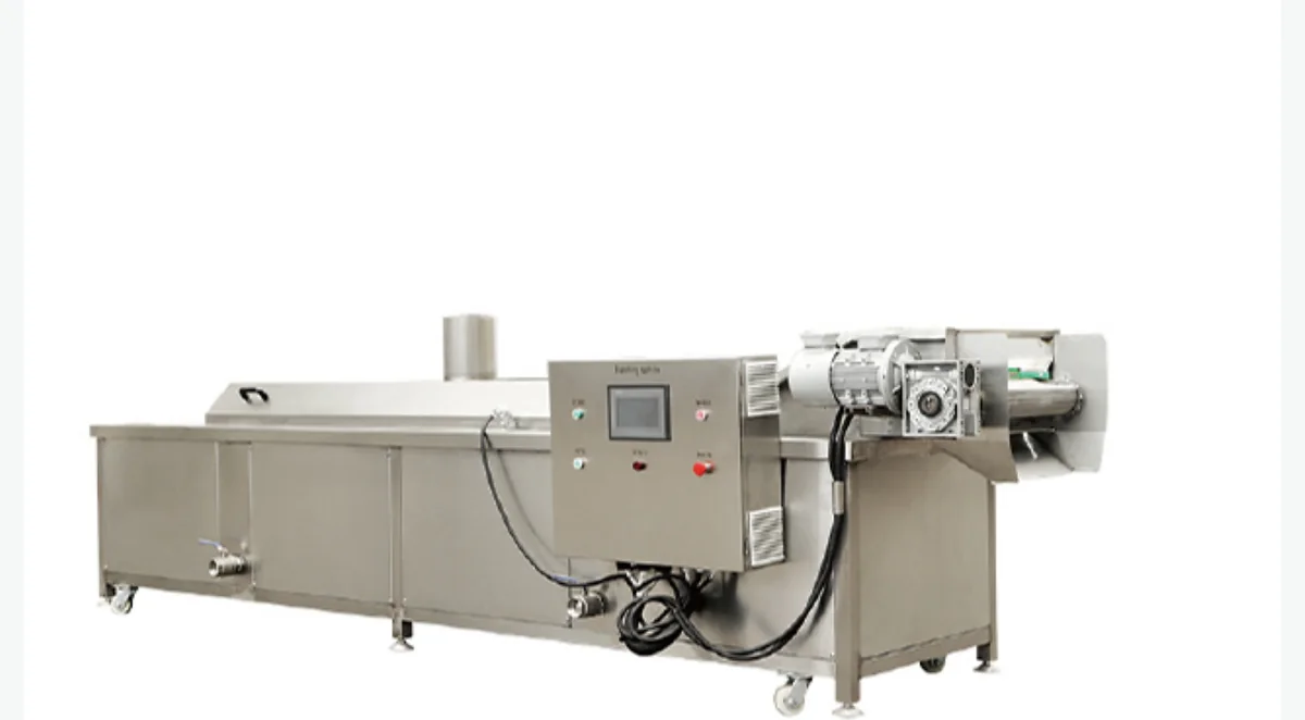
Higher output usually means larger modules and longer conveyor runs. As an indicative reference point for one module on the route, published dimensions for the continuous fryer range from 4000 × 1200 × 2400 mm to 8000 × 1200 × 2400 mm across the model range. Full dimensions for every other stage, matched to your configuration, are provided on request with the technical offer.
Buffer and hold points
Buyers sometimes shorten the drawing by removing buffer space between stages. This is where the difference between a drawing that looks efficient and a line that is easy to run appears: without working space for product transfer, sampling and cleaning between stages, operators end up working around the machines instead of with them. Reserving that space at drawing stage costs length; adding it later costs a rebuild.
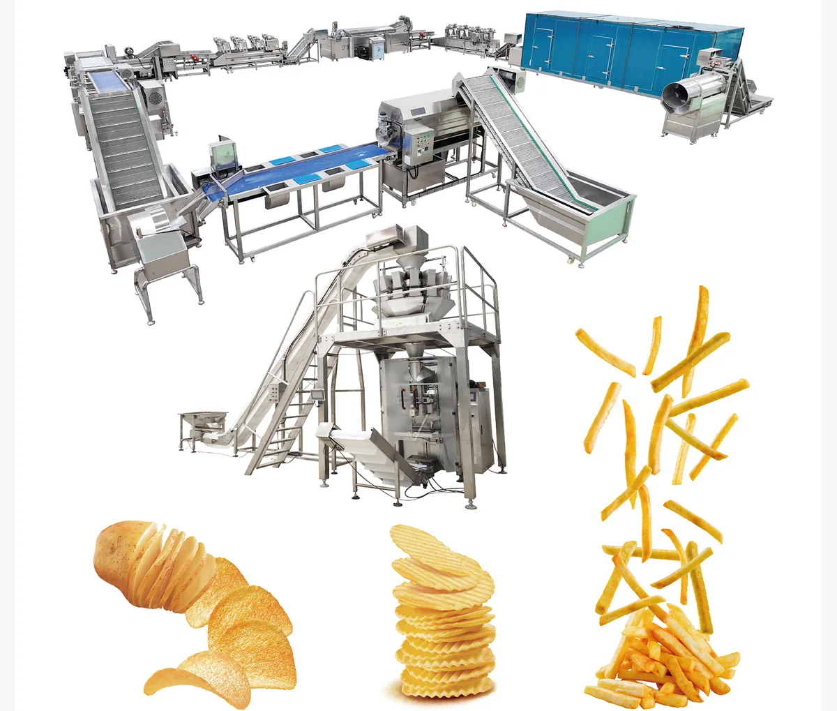
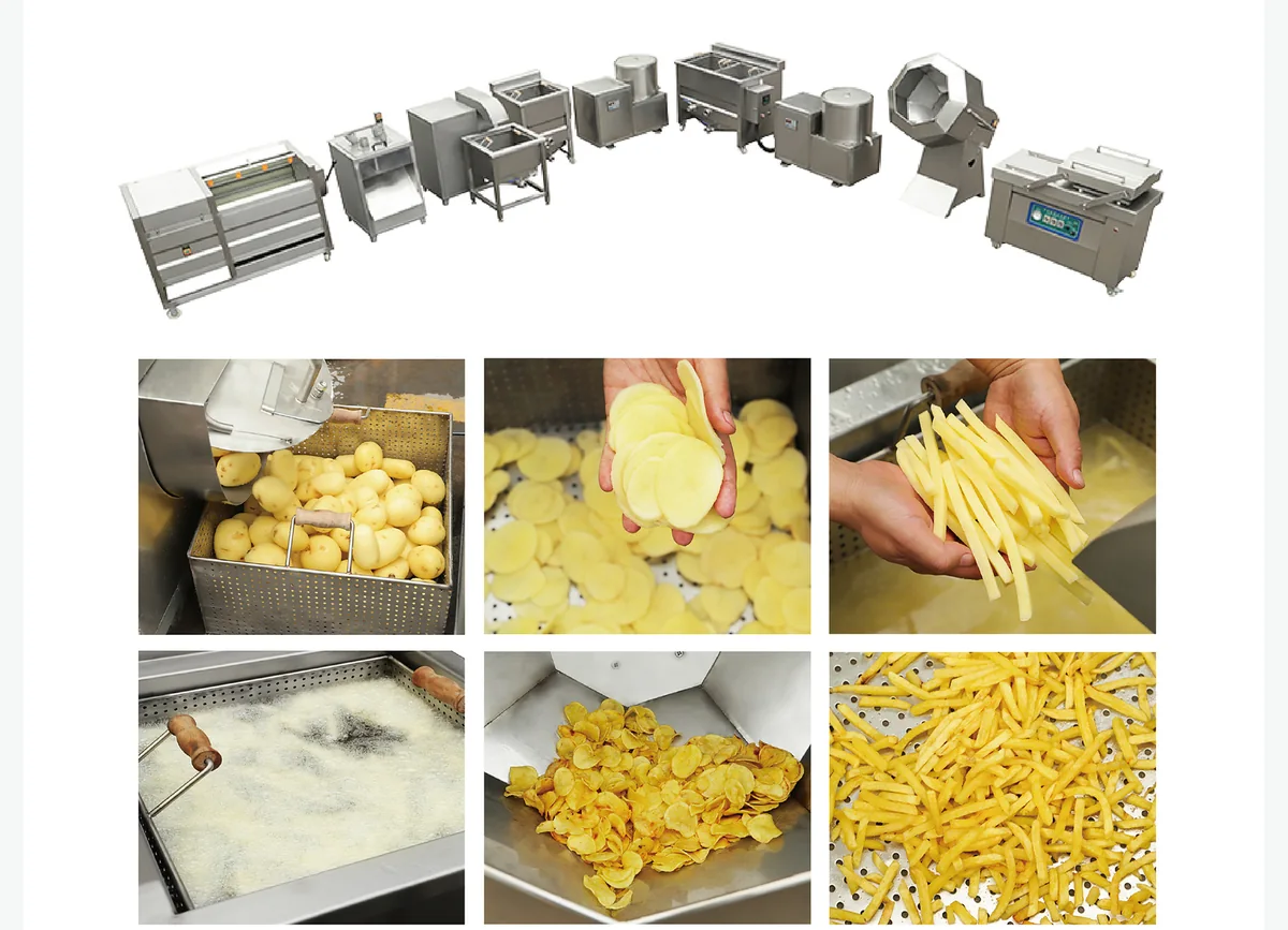
The current line configurations are shown on the automatic French fries and potato chips line page and on the semi-automatic configuration page, which is the shorter and lower-investment starting point for the same product family.
3. Clear height: check the tallest point first
Clear height is the vertical distance from the finished floor to the lowest obstruction above the line — a roof beam, a truss, a duct run or a sprinkler pipe. It has to clear the tallest point on the route with enough room for the maintenance operation that happens above the machine.
The tallest module is not always the obvious one. A frying stage with an exhaust hood, a blanching stage where product is lifted and dropped, and a feeding or transfer point that raises product to the next stage all add height. So does any overhead duct or steam pipe that has to be routed above the line.
Practical rule for the survey: measure clear height at several points along the intended route, not once at the door. Buildings with a sloping roof, a mezzanine or a beam grid can lose height exactly where the route needs it most.
4. Floor condition, slope and drainage
A fries line is a wet process at the front and a dry process at the back, and the two should not be arranged so that water travels through the dry zone. Drain positions decide much of the layout, because water — wash water, blanching discharge, cleaning water and condensate — has to reach a drain by the shortest sensible path.
Four items are worth confirming with the building survey:
- Drain positions and depth. Existing channels, their capacity and their cover level constrain where wet stages can sit.
- Floor finish and slope. Whether the floor is level, whether a fall already exists and in which direction, and whether the surface can be washed down.
- Floor loading. Whether the slab is suitable for the machines and for the handling equipment used to move them in.
- Clean and dirty zones. Where raw potato handling ends and where finished product handling begins, so that the two never share a walking route.
Water and drainage planning for a processing line runs wider than the fries line itself. The utility planning guide covers the supply side — power, water, fuel and drainage connections to settle before delivery — and the utility entry points should be marked on the same drawing as the layout.
5. Column grid and the direction of material flow
Columns are often what makes an otherwise workable layout impossible. A route that has to pass between two columns at a fixed spacing may not accept the widest module in the sequence, and moving the module is usually harder than accepting a shorter stage or a different flow direction.
Survey the column grid before drawing the route, and draw two possible flow directions on the same plan: a straight run and an L-shaped run. In many existing buildings the L-shaped arrangement fits better, because it uses the building's width instead of demanding its full length. Once the flow direction is fixed, feeding position, packing position and the finished-product exit all follow from it, and so does the position of every operator station.
6. Access aisles and maintenance clearance
Machine footprint is not the space the line uses. Every stage has a service requirement: panels that open, parts that are lifted out, wear parts that are replaced and surfaces that are cleaned between shifts. A layout that allocates only the machine footprint leaves no room to actually do that work.
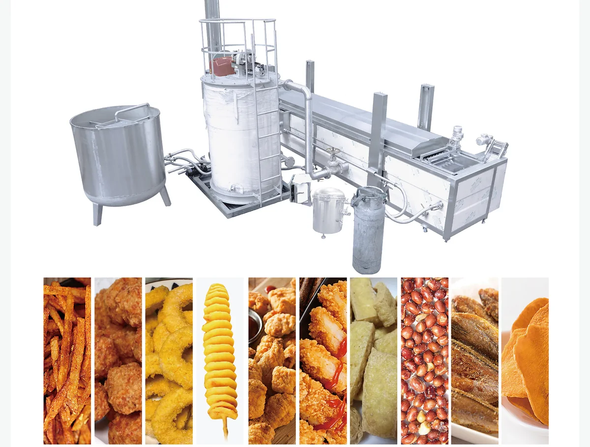
Draw the service envelope around each stage rather than a single rectangle. For the frying stage, for example, the continuous belt fryer page lists the machine's working dimensions, but the access requirement around it — for cleaning the belt, changing oil and reaching the drive end — is a project item to be confirmed with the technical review. The same applies to the blanching stage and every other module in the route.
7. Door openings and the installation route
A line that fits the room but cannot be carried into it is still a project at risk. The installation route has to be checked from the unloading point to the final position, including every door, corridor, ramp, stairwell and turn on the way. Door width, door height and the turning radius at each corner are the practical limits.
If the largest module cannot pass, the options are limited and all of them cost something: part-shipment and on-site assembly, a different module size, or a modification to the building opening. Checking this before the order is placed is why suppliers ask for photographs of the access route and a dimensioned drawing rather than a verbal description.
8. Where power, water and steam enter the building
The entry points of electricity, water, steam or fuel and drainage decide where the heavy-consumption stages should sit. Routing services across the full length of the line instead of to the nearest suitable point adds material, work and lifetime maintenance.
Mark on the drawing: the main electrical panel position and available load, the voltage and frequency available at site, the water source and pressure, the heating source for the frying stage, the compressed-air position if the line uses it, and the drainage route. Confirm the actual values with the site survey — this site's machinery dimensions and utility requirements are provided on request and reviewed against the real site conditions, not assumed from another project.
9. Reserve space for phase two
Many fries line projects start with a shorter route and add stages later: freezing after chilling, or packing automation after manual packing. If that is the plan, the reserved space has to be decided now, because the stages that are added later need length, clear height, drain positions and electrical capacity that may no longer be available once the first phase is installed.
Two practical measures: mark the reserved corridor on the layout drawing and keep it clear of storage and pallet positions, and reserve the electrical and drainage capacity for the future stages even if the machines are bought later. A reserved corridor that exists only as an intention disappears the first month the factory is short of space.
10. What to send to confirm a layout
A layout can be reviewed properly from a small, specific set of documents. Sending them together shortens the review noticeably, because the questions that would otherwise come back by email are answered in the first exchange.
- A dimensioned plan of the available area, including columns and their spacing
- Clear height at several points along the intended route, and the position of beams or ducts above it
- Door and opening dimensions along the installation route, with photographs of the access path
- Drain positions, floor condition and the wastewater route
- Power supply, available load, voltage, frequency and the position of the main panel
- Water source and pressure, and the heating source available for frying
- Intended process route, target output, working hours and finished product format
- Whether a second phase is planned, and which stages it would add
Once these items are on the drawing, the layout discussion becomes a review of a specific arrangement rather than a general conversation. The RFQ checklist covers the project information that belongs alongside these drawings, and the cost factor guide explains why two quotations for what looks like the same line are not comparable until the route and scope behind them are stated in writing.
Layout review checklist
- Process route fixed before the building survey
- Capacity tier and working hours agreed
- Clear height measured at several points, not only at the door
- Drain positions, floor fall and clean/dirty zone split marked
- Column grid drawn and flow direction tested two ways
- Service envelope allowed around every stage, not only the footprint
- Door widths and turning radius verified along the installation route
- Power, water, heating and drainage entry points positioned
- Phase-two corridor and reserved capacity marked on the drawing
- Lifting and special transport requirements reviewed for the largest module
Frequently asked questions
How much floor space does a French fries line need?
There is no single number. The footprint depends on the process route, the capacity tier, the number of intermediate stages, the height of the building and how the buyer wants to arrange access and buffer points. A layout can only be confirmed against a dimensioned building drawing, and final dimensions are reviewed with the technical offer.
Is clear height or floor area the more common constraint?
Both appear regularly, but clear height is the harder one to change. Extending a building sideways is usually more practical than raising a roof, so the tallest point on the route should be checked before the layout direction is fixed.
Can a fries line be installed in an existing building?
Often yes, provided the door openings, installation route, floor condition, drainage positions and clear height allow the largest module to be moved in and serviced afterwards. These items are checked from drawings and photographs before a layout is proposed.
Should expansion space be reserved from the beginning?
Where a second phase is likely, reserving length, height, drainage and electrical capacity at the planning stage costs far less than relocating a commissioned line later. The reserved corridor has to be marked on the drawing, not left as an intention.